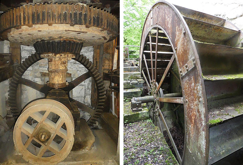
We recently surveyed a magnificent watermill in Stamford, Lincolnshire, one of some 5,000 mills recorded on different sites by the Domesday Book in 1089. Stamford became established since it was the lowest point at which the river could be forded by the Romans on Ermine Street. The river was also navigable as far as Stamford and later improved by canal when trade was carried in keels and barges. The current watermill building dates from around 1640 and is built of sandstone and predominately roofed with Colley Weston slate tiles. It has twin undershot water wheels, on the north and southern walls respectively, which seem to have been engineered to run in tandem. There were four grinding burr and grit wheels and much of the original equipment is still in situ.
Whether windmill or watermill, the miller was generally paid in flour – typically a 1/16th share of what he milled – and invariably, this was under-declared to reduce the payments to the Lord of the Manor. The hard-working miller was lambasted by Chaucer who wrote –
‘He was a master’s hand at stealing grain. He felt it with his thumb and thus he knew its quality and took three times his due – a thumb of gold by God to gauge an oat’.
By the 1700s, the design for watermills concentrated on the effects of the impact on the blades and the overshot wheel where the water supply was taken up to the crown (top of the wheel). A breast-shot wheel, where water pours onto the wheel roughly in line with the axle, probably dates from around 1850 but here, these are undershot wheels, initially turned by the force of the water alone against the blades. Later, boxes were formed on the top of the floats to carry water forwards and so add to the torque. Thirty 42-inch wide paddles are bolted together, plus fishplates, to create 14-foot rings with a dozen steel bracing spokes. Iron was used to replace wood, particularly with shafts and gears, not least because the wooden equivalents quickly wore out.
A site such as Kings Mill, purportedly named for King John, was only suitable for an undershot wheel because of the surrounding geography. Here, water was fed into the wheel, controlled via a simple up-and-down sluice gate, and the kinetic energy created by the entry speed was exchanged for weight within the wheel buckets and subsequent energy. As the wheel turned, so the weight of the water dropped from the blades into the tail race with relatively little forward velocity.
Originally, watermills were used primarily to produce flour. The idea of using two stones which revolved, one on top of the other, was developed here by the Romans. The basic principle was that grain went through a hole in a gap between the stones and rotation ground the seed to a simple flour. Early on, it was realised that if the stones had grooves cut into the top (course dressing) the grain was broken down much faster. The grooves were cut at an angle to the edge of the stone, so that the action of one unit passing over the other was akin to a pair of scissors. Dressing these grooves in the hard stone was skilled work, often done by a
travelling stone dresser. It involved removing the hopper shoe, the supporting horse frame, and the tun or vat that encased the stone. This was no easy task, bearing in mind that a stone could weigh well over one tonne. Using chisels on the stone often caused them to spit fragments, so embedding themselves in the arms of the dresser; skilled craftsmen would often be judged by the extent of the marks on their arms, termed to be when he ‘showed his metal’. It was commonly held that the best burr stones were of French origin from pits outside Paris. Coarser stones were from Derbyshire grit. Later, runner stones were often ringed with iron bands known as tyres. Composite materials were also used including plaster of Paris which incorporated four balance pockets where lead could be
added to balance the wheel. The gap between millstones was very small, generally being 1/50th to 1/100th of an inch and it was critically important to maintain an even flow of grain. If the stones were to touch, they could easily grind to extremely hot temperatures and catch fire – a major hazard in a flour dust environment which could literally explode. A simple bell and string alarm was therefore established, which was activated when the grain ran dry.
A standard configuration was a pit wheel (a vertical upright) meshing with a horizontal wallower attached to a spur wheel which, in turn, drove the stones and any auxiliary drives via a top crown wheel. The wheel shaft, if timber, would undoubtedly be oak and later cast iron, carried on two wooden bearing points which had to be well greased to avoid friction. Wooden teeth were used on the internal apparatus, known as cogs. The drives were usually involved in either powering the stones or driving auxiliary machines such as grading sieves and sack hoists. The top stone was called a runner and mounted on a hat shaped saddle or rynd. The damsel fitted on to this casting at right angles to the rynd and the runner stone on top of that was not turned until grain was fed through. The gap between the
stones was controlled by raising or lowering the bridge tree, also known as a ‘tenter’, which carried the drive shaft – this operation was therefore called ‘tentering’. A number of mechanisms existed to disengage the drive, but here the method was to move the top of the drive shaft out of its bearing and hold it in an iron ring. Simple!